Modeling a 2026 F1 Car from Scratch with GSD in 3DExperience
Using Generative Shape Design in 3DExperience, I successfully modeled the sidepods and rear wing of a 2026 F1 car by creating points, cross-sections, splines, lofts, and trimmed surfaces, with plans to build the complete 2026 F1 car model in future steps.
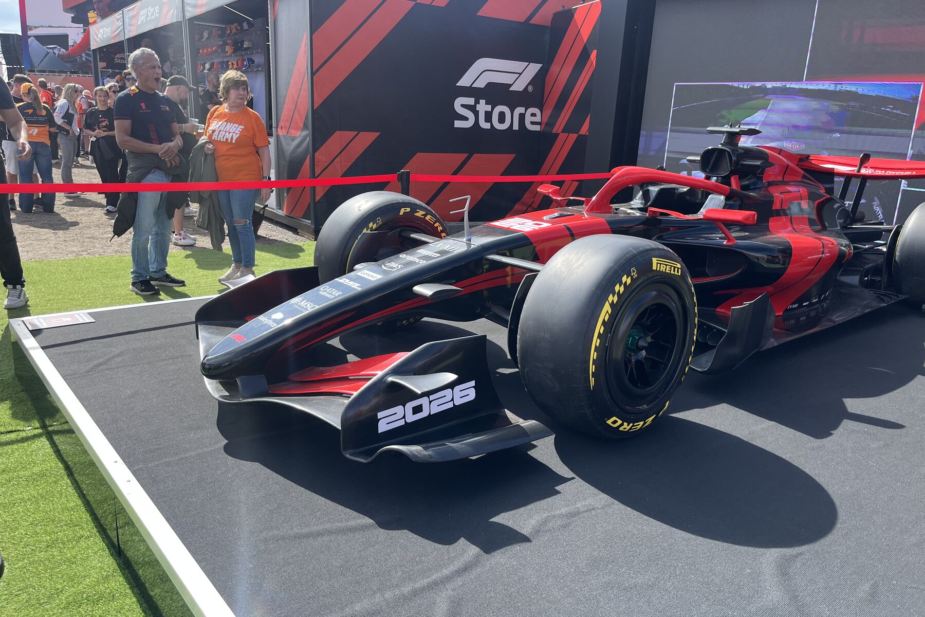
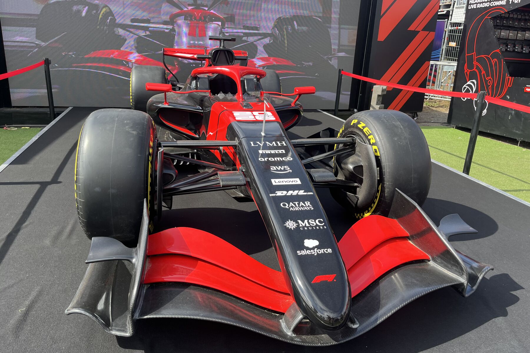
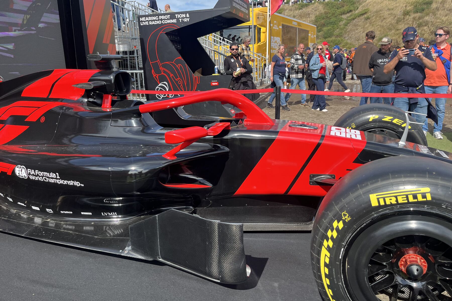
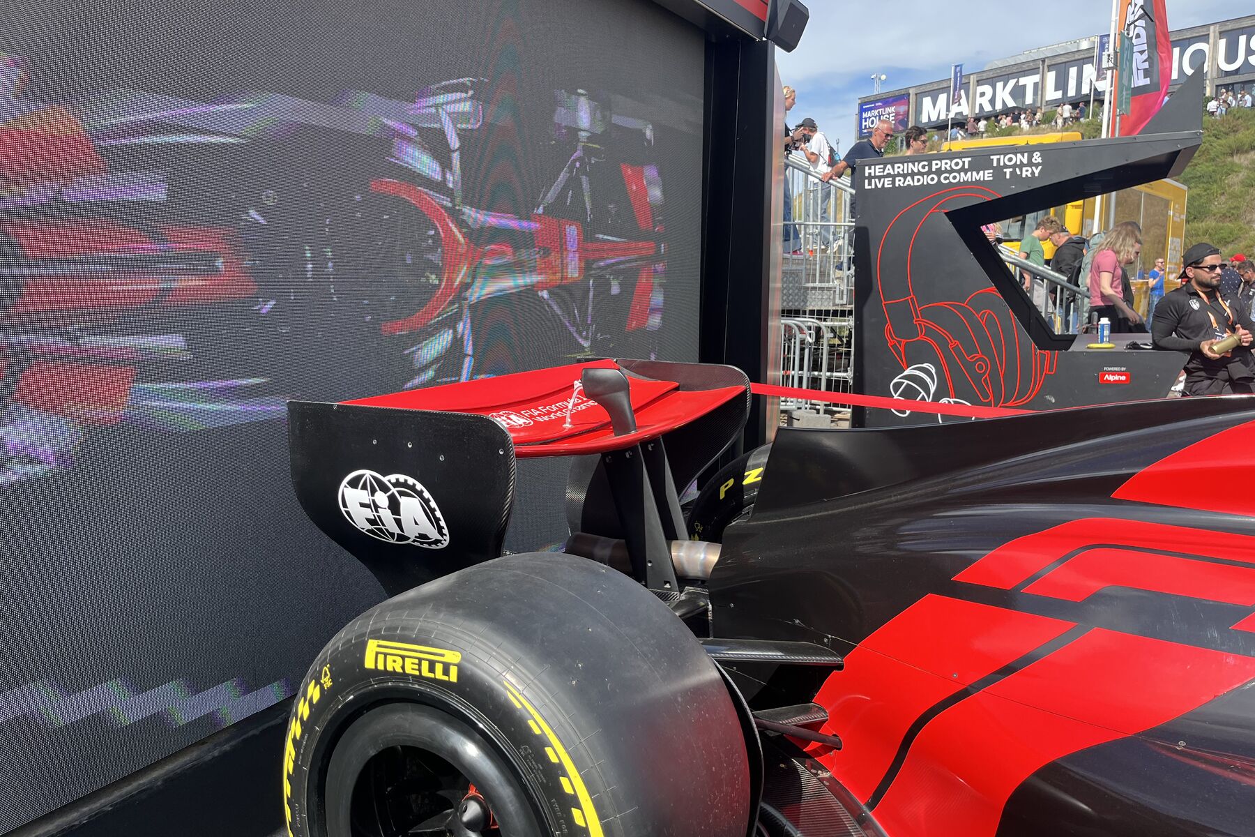
After attending an F1 race in person and getting an up-close look at a 1:1 scale model of the 2026 F1 car, I decided to reconstruct the 2026 F1 car in 3DExperience.
References
My project was inspired by Ted L’s article “I Built an F1 Car — The 2026 Regulations”. It is a very in-depth article from which I learned a lot. The original post documents how the author built geometry, balanced regulatory trade-offs, and conducted CFD analysis from a full-car perspective based on the new 2026 regulations.
I followed a similar approach. My plan is to break the car down into distinct components, complete the modeling for each component individually, and finally run CFD simulations to validate the differences between my model and the real car.
First, I targeted the sidepods as my initial focus. Starting in a clean project, I built points, surfaces, section curves, support surfaces, and structural surfaces from scratch. Then, I used the same methodology to create the rear wing.
Approach to Building the Skeleton from Scratch
First, I established the center plane of the vehicle and a set of reference planes distributed longitudinally along the body, with the center plane controlling left-right symmetry.
The longitudinal planes hold the cross-sections of the sidepods (the same approach was used later for the rear wing). Horizontal and transverse planes were used to define the floor height, endplate positions, and spatial relationships between various surfaces.
Since the bodywork is symmetrical, I only needed to model one side during the design stage and mirror it across the center plane at the end.
In GSD (Generative Shape Design), I categorized the specification tree by modeling function rather than dumping all objects into a single Geometrical Set. This kept the current structure organized and made it easier to expand into a more complex full-car project later. The table below summarizes each group and its purpose:
| Group | Content |
|---|---|
| Reference Datums | Vehicle center plane, longitudinal stations, horizontal and transverse control planes |
| Construction Points | Section feature points, boundary endpoints, and local control points |
| Curves | Cross-section splines, guide curves, and closed boundaries |
| Support Surfaces | Multi-Sections Surfaces, Fills, and local extension surfaces |
| Trim & Join | Split, Trim, Boundary, and Join operations |
| Final Results | Verified sidepod and rear wing surfaces retained for output |
With this structured approach, every surface can be traced back to its underlying cross-sections and boundaries. When modifying a local area, I only need to adjust the corresponding points or splines without recreating the entire component. I also assigned clear names to each component and construction object for easy retrieval.
Basic Modeling Workflow in GSD
Each surface region followed the same construction sequence:
Reference Planes
→ Construction Points
→ Section Splines
→ Guide Curves / Closed Boundaries
→ Multi-Sections Surface / Fill
→ Split / Trim
→ Join
→ Symmetry
For planar end faces and closed contours, I used Fill to generate surfaces. For freeform surfaces, I relied primarily on sets of cross-section splines. Where transitions between sections were smooth, I connected them using Multi-Sections Surface. However, in areas with sudden curvature changes or rapid contour contraction, I split the region into smaller adjacent surfaces and merged them using Join. For regions with cutouts/holes, I created the main support surface first, projected the inner loop onto it, and performed a Split.
I only completed the surfaces and Join for the right half before applying symmetry. This not only ensured an identical left side geometry but also eliminated the need to edit both sides simultaneously, guaranteeing that the symmetry plane remained driven by a single center datum.
Sidepods
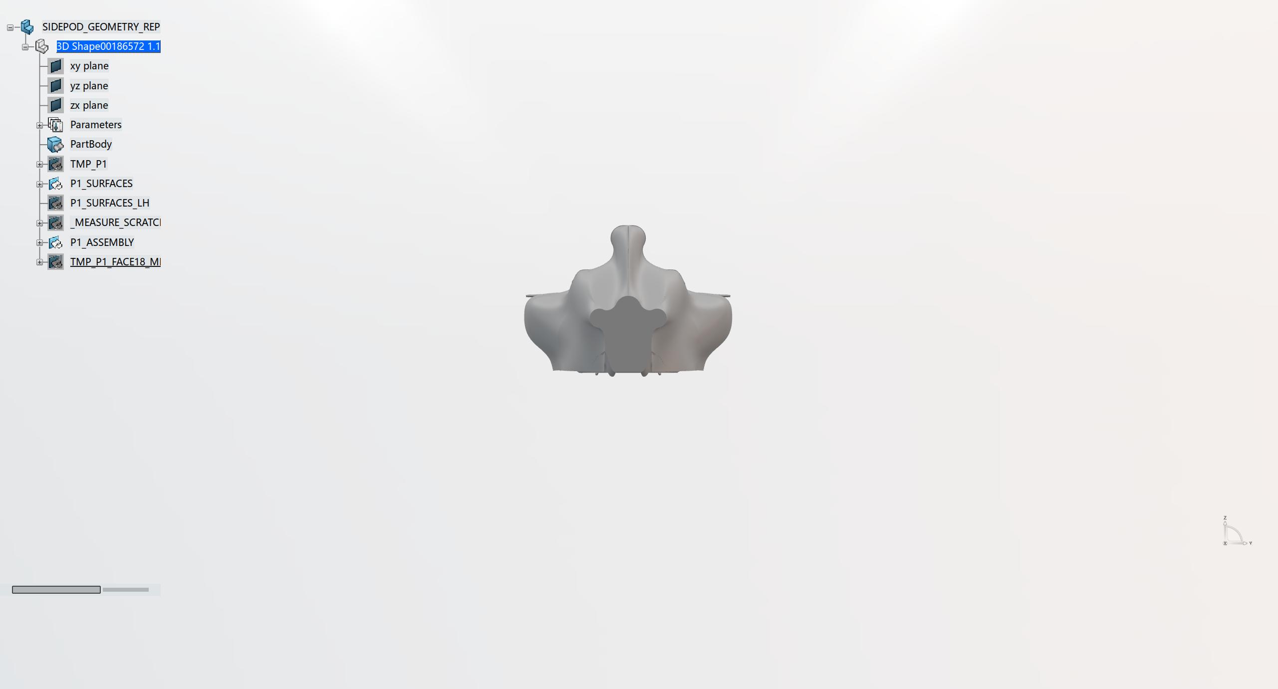
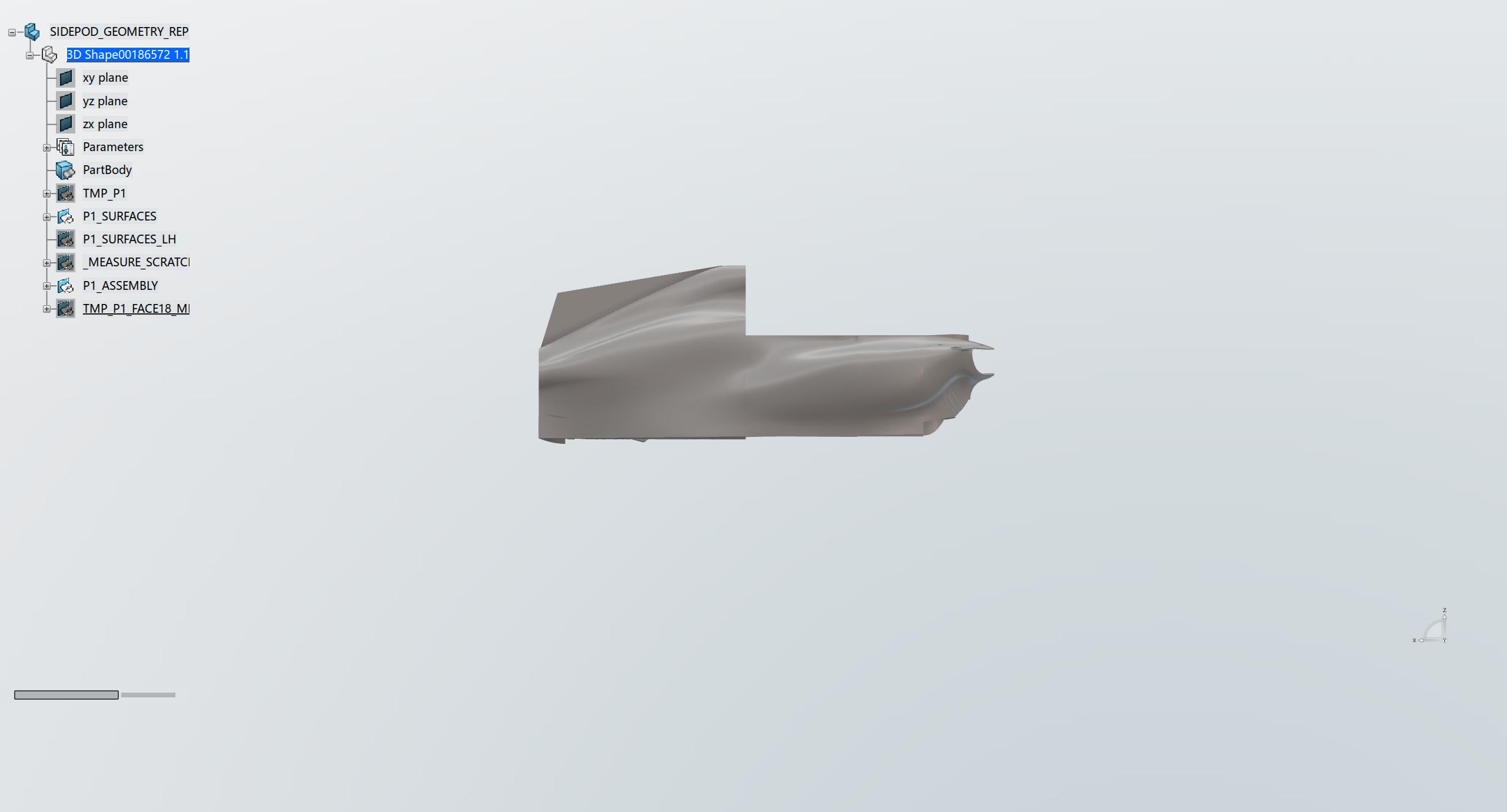
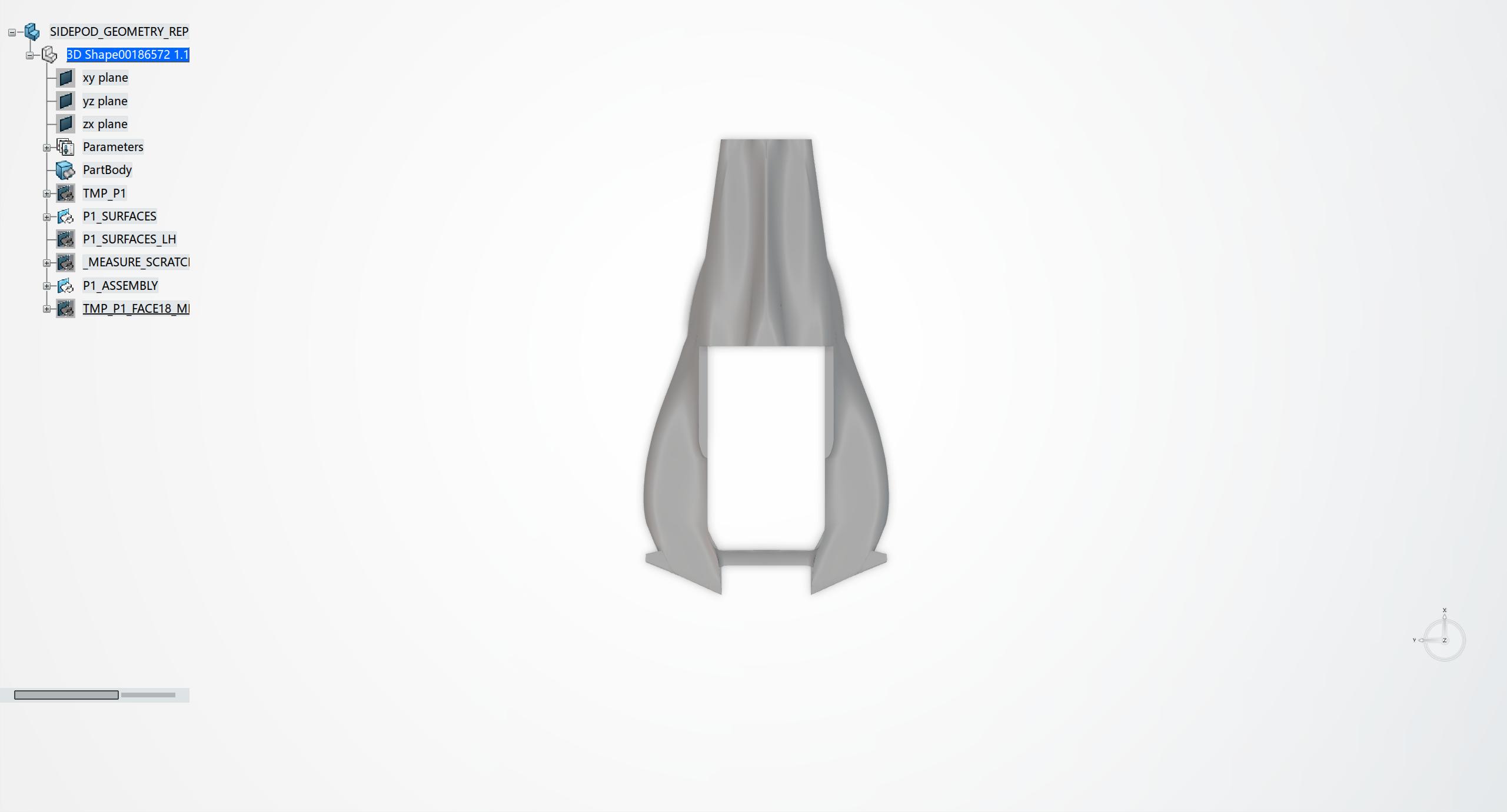
The sidepod is a highly complex, large-scale geometric body. I divided the overall structure into the inlet, shoulder, undercut, maximum width region, waist contraction, and rear transition. It is difficult to construct using a single large surface because the top, side, and bottom surfaces exhibit complex, varying curvatures at different longitudinal positions. After trying several methods, I arrived at a result I was satisfied with.
First, I created a series of station planes along the longitudinal axis of the body and placed contour points on each plane to define the inlet height, shoulder width, bottom contour, and rear contraction. The points at each station were connected via splines to form open cross-sections.
After completing the primary cross-sections, I used Multi-Sections Surface to build the core surfaces of the sidepod:
- The shoulder and rear transitions are relatively smooth and could be directly lofted using continuous cross-sections.
- The undercut and localized transition zones change rapidly, requiring additional local cross-sections.
For planar capped areas and local transitions, I used the following techniques:
- Flat end faces and local planar areas were created using closed splines paired with Fill.
- Narrow closed regions were patched section by section according to their boundaries.
- Where adjacent sections changed rapidly, I split the area into a series of two-section surfaces and combined them into a continuous surface using Join.
This breakdown maintained the overall volume of the sidepod while allowing independent modifications to the inlet, shoulder, undercut, and rear section. Finally, I mirrored the completed right side to the left.
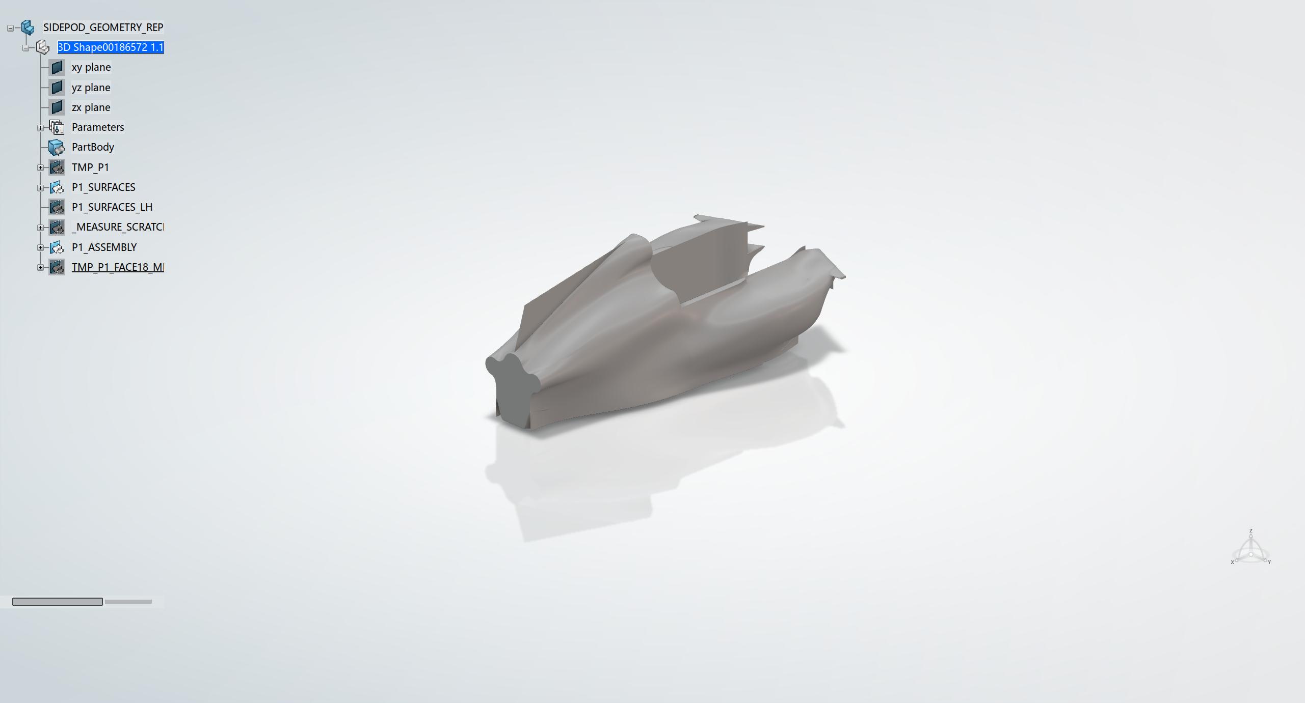
Below are screenshots of the modeling results:
Rear Wing
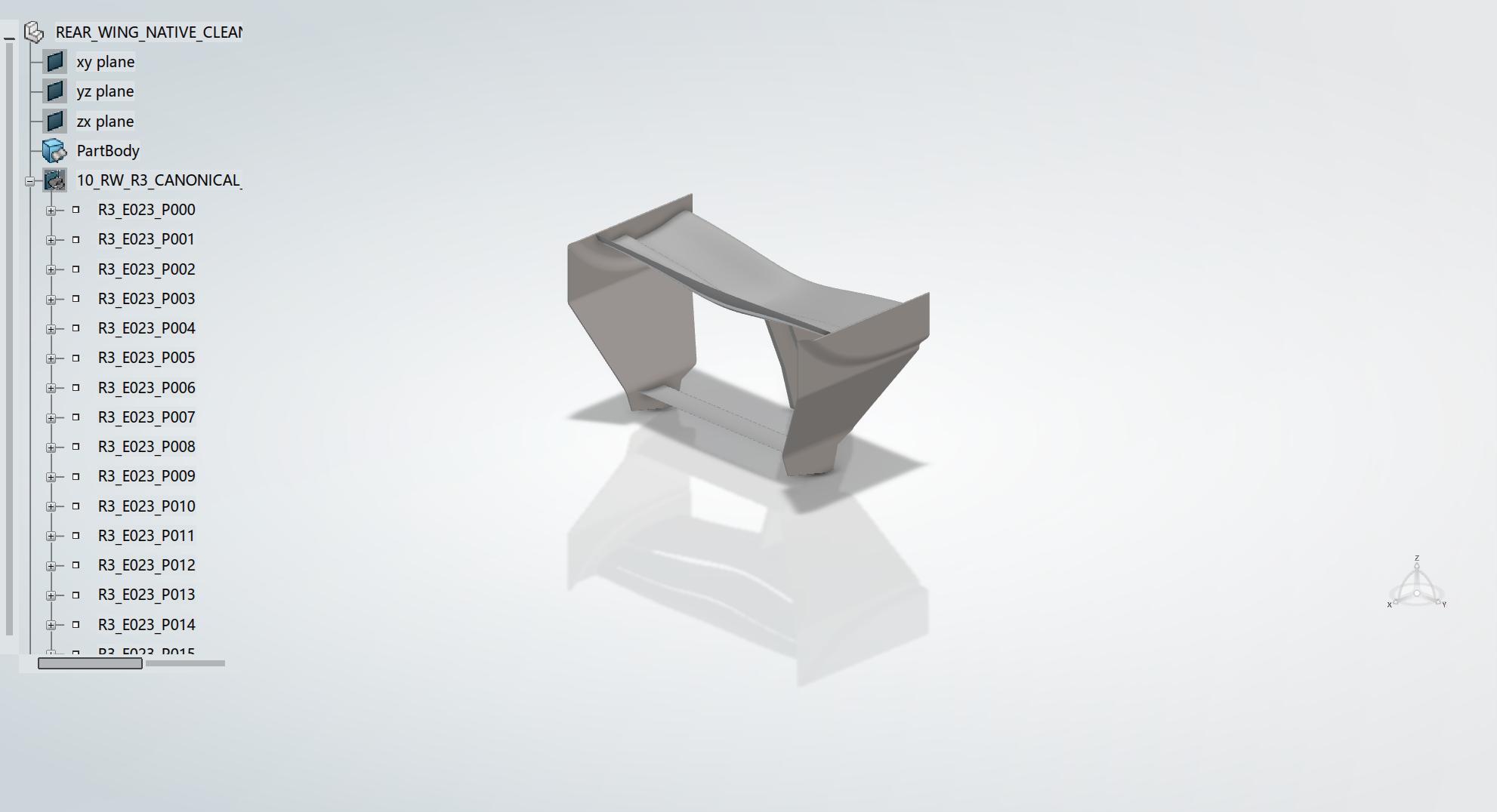
The structure of the rear wing differs from the sidepods. It primarily consists of the mainplane, movable flap, endplates, central pylons/supports, and local transition surfaces. I still built each functional area first before verifying the connections between them.
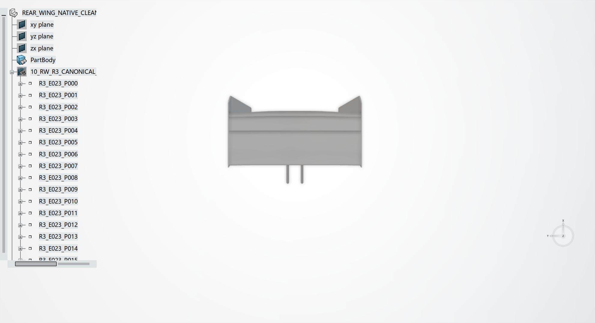
For the mainplane, I established cross-sectional splines at different spanwise locations and connected them using Multi-Sections Surface. When extra control was needed at the wingtips or central section, I added endpoint guide curves to constrain the boundary trajectory. The flap used an independent set of cross-sections to preserve its distinct position and angle relative to the mainplane.
Endplates
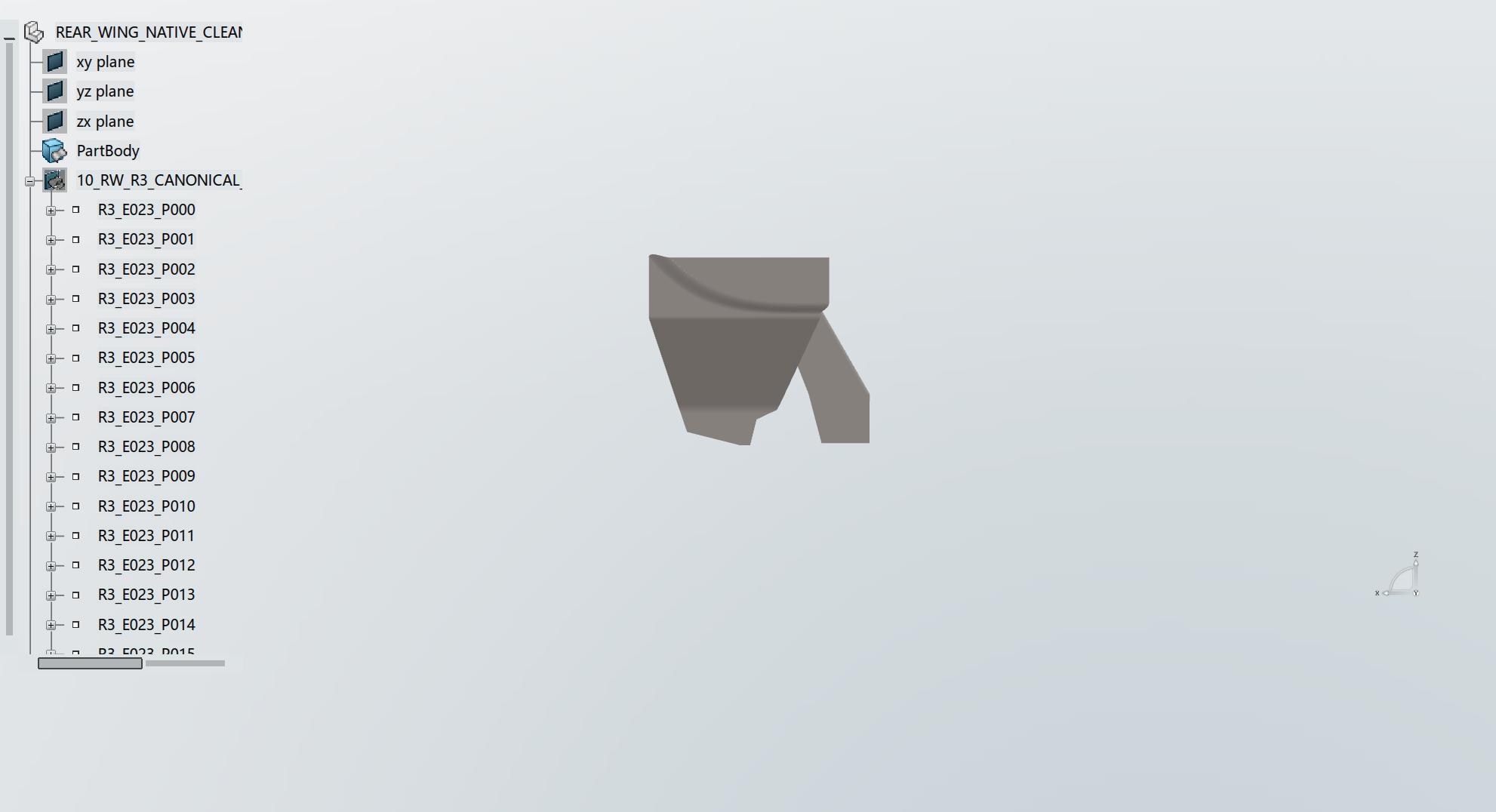
For the endplates, I first built the outer profile on a support surface, then used Fill and trimmed surfaces to create the main body. For cutout areas, I built the outer surface first, projected the inner loops onto the support surface, and applied a Split. This ensured that holes were part of the trimmed surface structure rather than floating construction lines.
For the central support pylons and local transition surfaces, I used planes, extruded surfaces, and Fill operations. After finishing all main elements—fixed wing planes, flaps, endplates, and supports—I performed a final Join and Symmetry to obtain the complete rear wing assembly.
Screenshots are shown below:

Remaining Work
After completing the sidepods and rear wing, I will apply the same approach to finish the remaining components:
| Modeling Area | Planned Scope |
|---|---|
| Front Wing & Nose Cone | Mainplane, flaps, endplates, nose transition, and local connections |
| Floor & Diffuser | Main floor, edge structures, throat section, diffuser section, and fences |
| Front & Rear Suspension | Upper/lower wishbones, pushrods, track rods, and their aerodynamic fairings |
| Suspension Deflectors | Local deflector surfaces ahead of and behind the tires |
| Quadruplane | Multi-tier deflector wings and their supports |
| Side Mirrors | Mirror housings, stalks, and mounts to the sidepods |
| Power Unit & Gearbox Packaging | Internal packaging envelope for the engine cover and rear bodywork slimming |
| Cockpit & Halo | Cockpit opening, headrest area, Halo structure, and bodywork transitions |
| Tires & Wheels | Front/rear tires, wheel rims, and contact patch geometry |
| Driver Helmet | External geometry for cockpit flow blockage |
| Wind Tunnel & CFD Domain | Ground plane, inlet, outlet, and far-field domain geometry required for computation |
CFD Planning
Similar to the article I referenced, after completing the full-car CAD model, I plan to run full-car CFD simulations using OpenFOAM. Given the potentially massive mesh count, I may need to consult my professors or seek sponsorship to secure sufficient computational resources.
First, however, I will start by testing individual components. My current plan is to begin with the sidepods and rear wing:
- Sidepods: Focus on incoming flow at the inlet, flow paths around the shoulder and undercut regions, and the wake effect of the rear section on the rear tires and engine cover.
- Rear Wing: Focus on aerodynamic loading across wing sections, slot gap flow, endplate vortices, and interference from the central support.
For the subsequent components—front wing, floor, suspension, and wheels—I will maintain consistent inlet conditions, ground/tire settings, and post-processing metrics. Standardizing these parameters ensures that differences in results stem primarily from the geometry itself rather than variations in domain or boundary conditions. Each component will be evaluated in an isolated setup for mesh quality, pressure distribution, surface streamlines, separation zones, and major vortex structures.
Ultimately, I plan to conduct a full-car study to analyze the interactions between upstream and downstream components. I know there will be many challenges, and isolated component results cannot substitute for full-car dynamics. However, analyzing individual components helps in understanding the role of each area. The final goal remains integrating all surfaces into a complete car model to investigate the coupling effects between the front wing wake, tire wakes, floor, sidepods, and rear wing.
To be continued. Updates will be posted here as the project progresses.