Reconstructing a 3D Spacecraft Model in Blender from ESA Blueprints
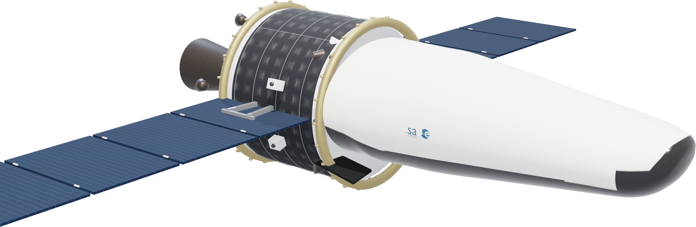
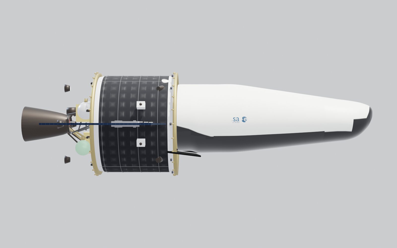
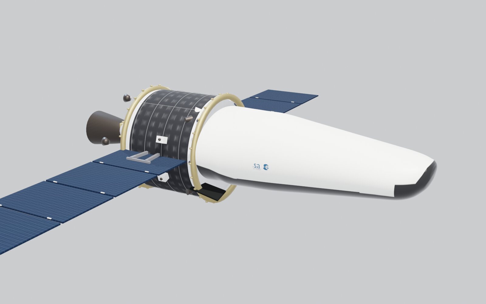
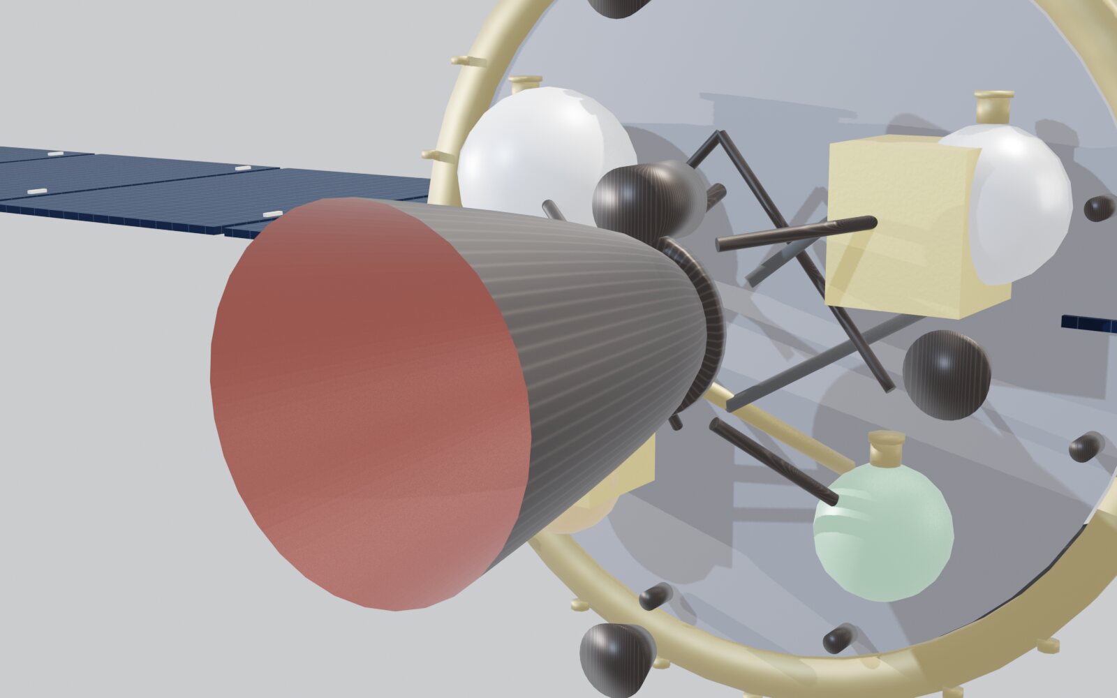
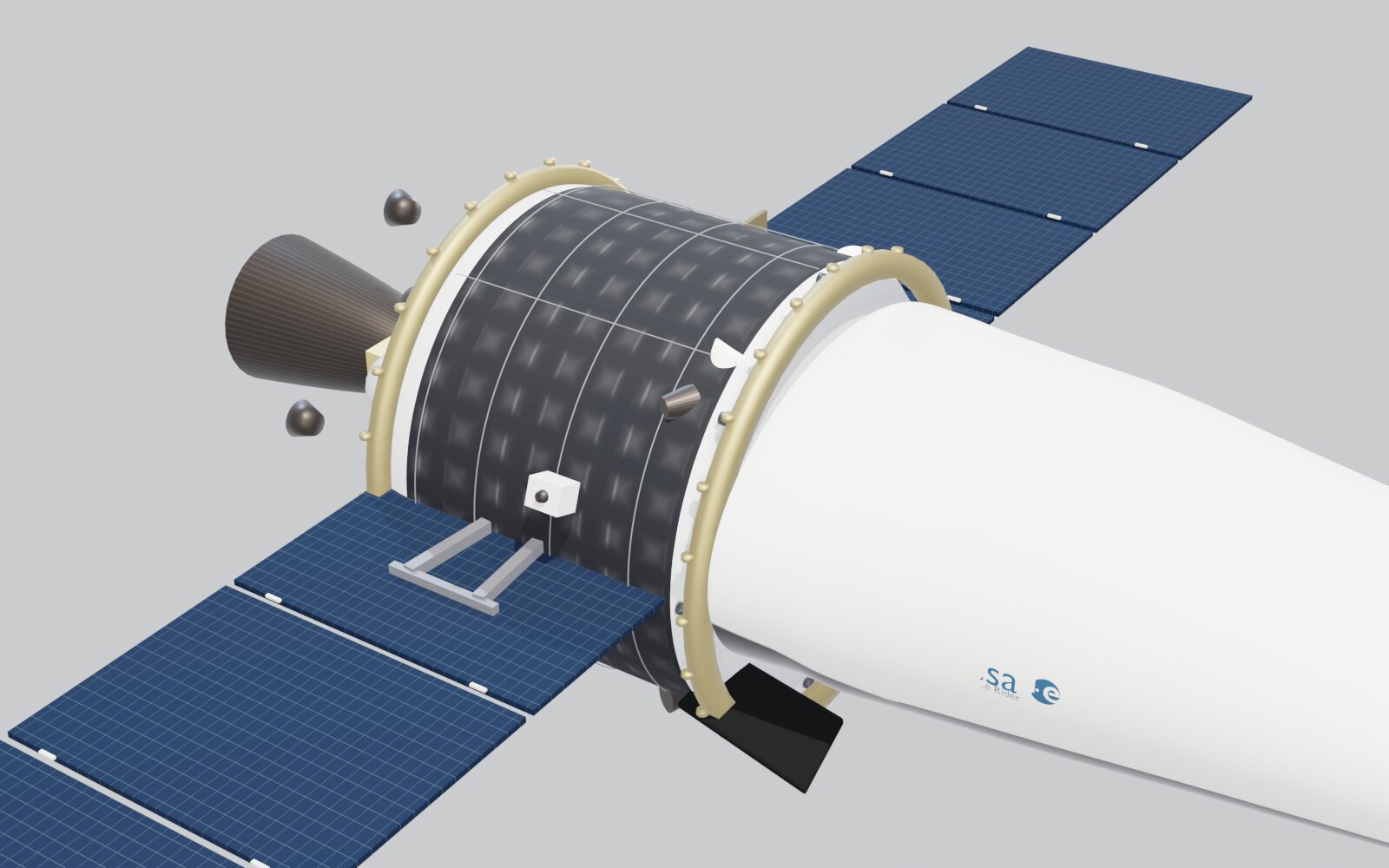
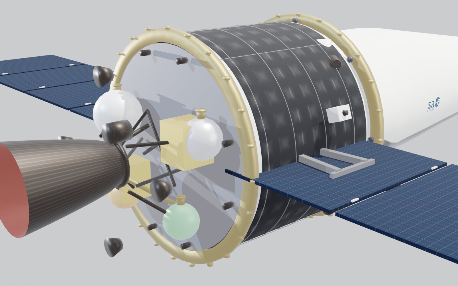
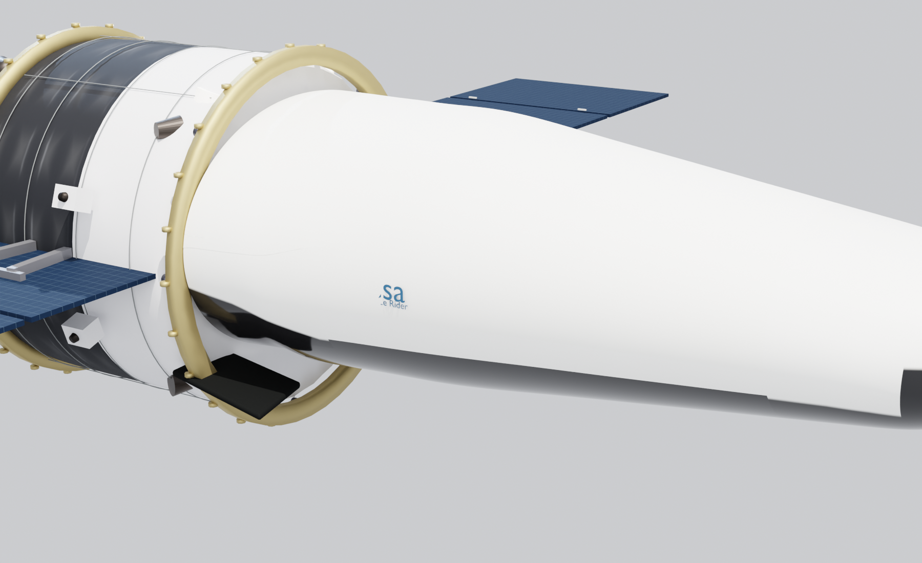
During my 17-week internship in 2026, I reconstructed a 3D model of the Space Rider spacecraft in Blender based on publicly available European Space Agency blueprints and technical documentation.
Project Overview
From April to August 2026, I completed a 17-week internship at Felisiak Ingénierie & Développement in Paris. The company was building a 3D asset catalog for Europe’s Spaceport in Kourou, French Guiana, enabling engineers to inspect launch vehicles, launch pads, ground facilities, and operational workflows directly within mission review applications.
Space Rider was my first full modeling assignment, as well as the most critical one. At the time, the company had only a rough polygonal mesh with roughly correct proportions but lacking accurate surface curvature and fidelity (which I ultimately discarded rather than built upon).
In short, my task was to reconstruct an accurate 3D model of the Space Rider spacecraft in Blender using exclusively publicly available documentation, targeting a geometric tolerance of approximately 10 cm.
Reference Materials
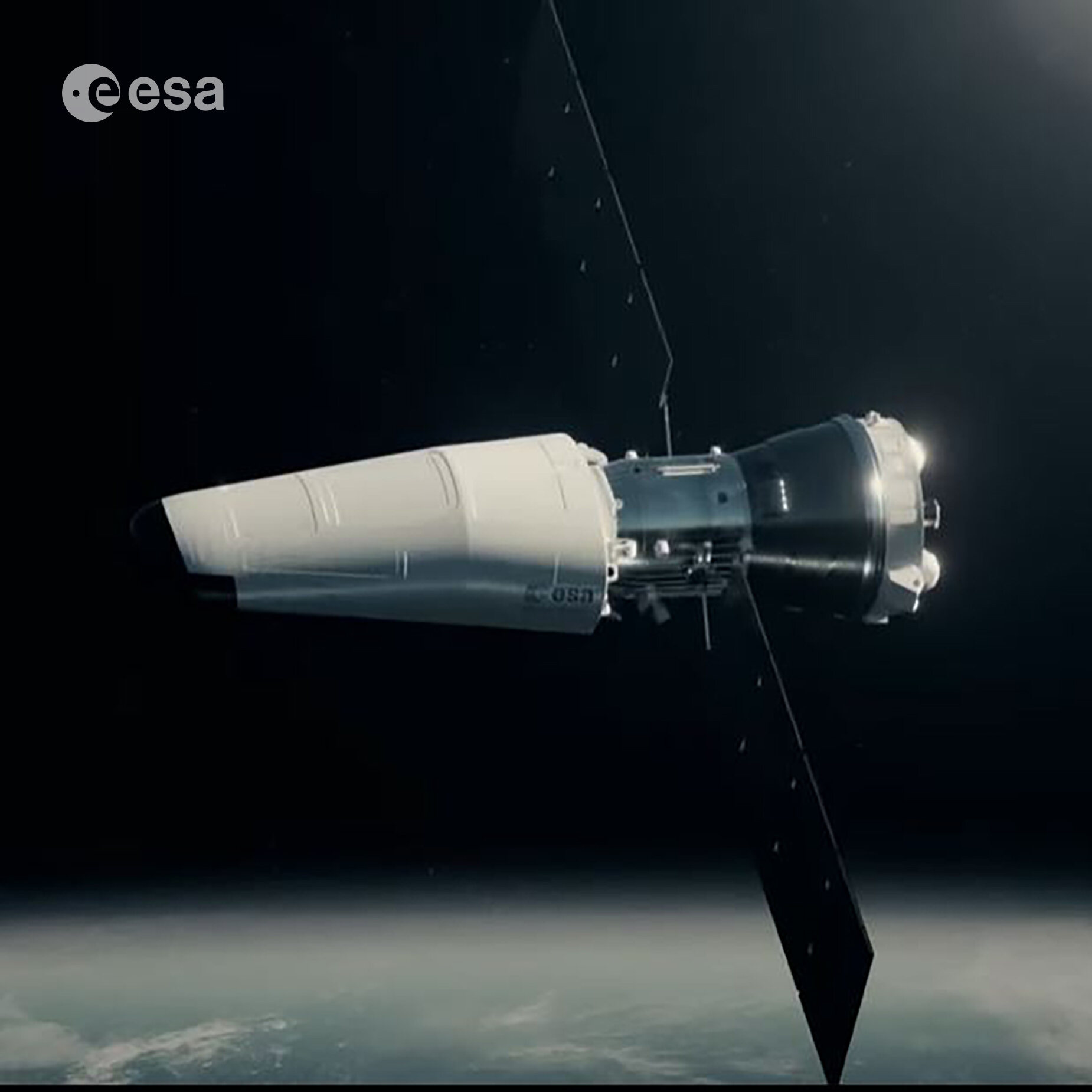
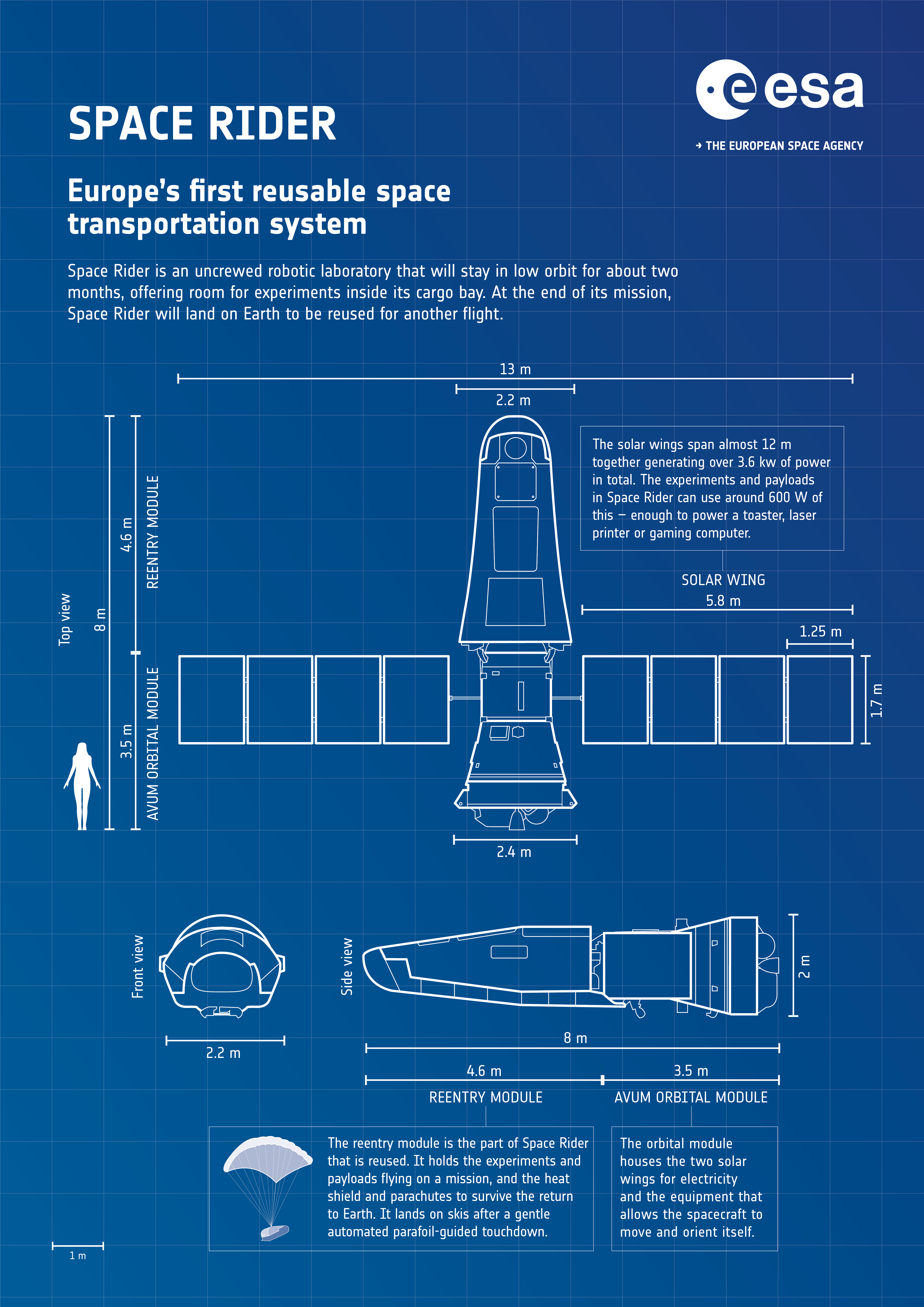
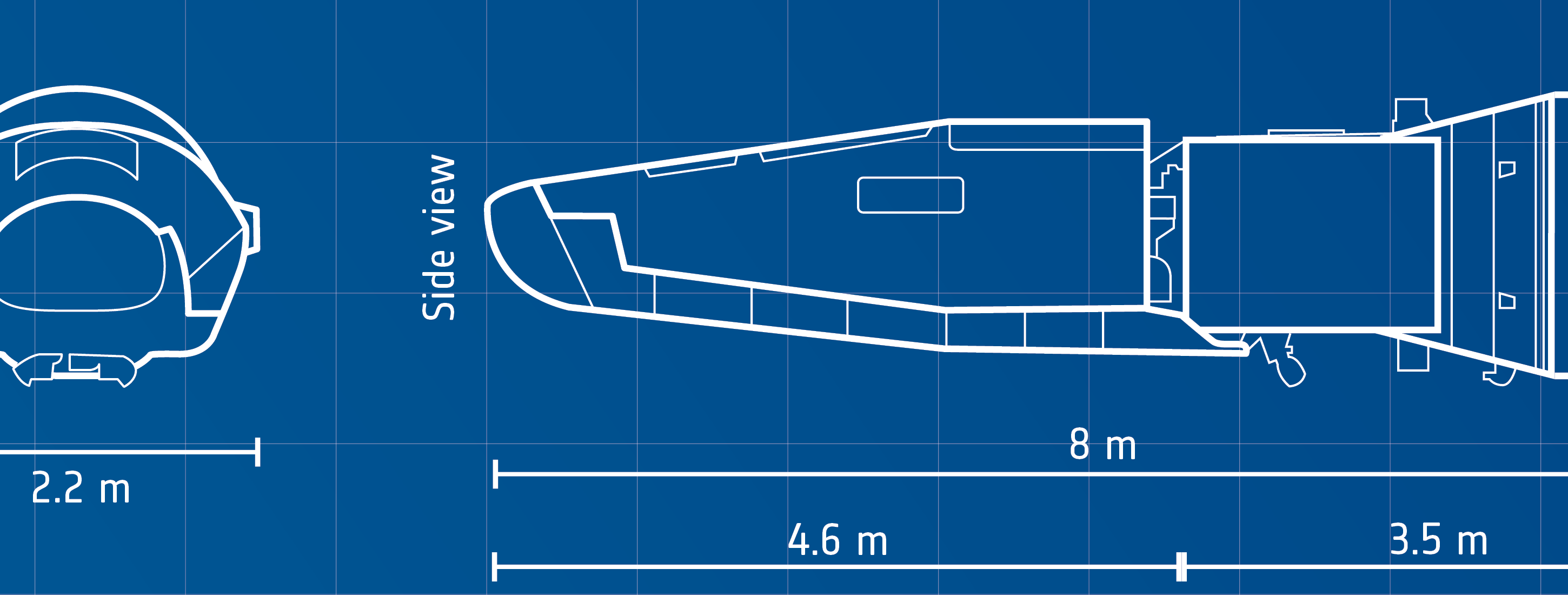
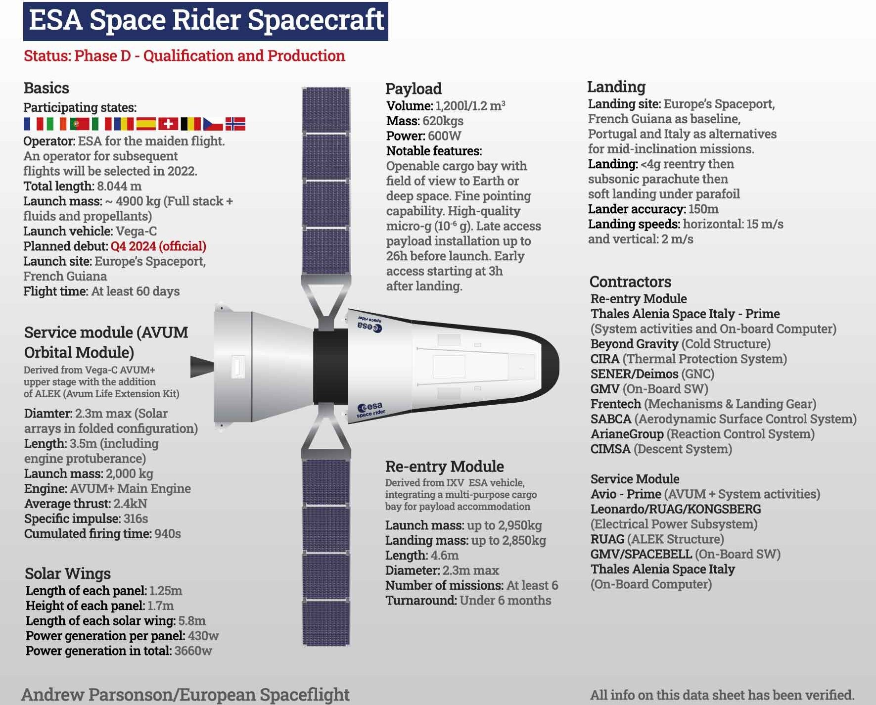
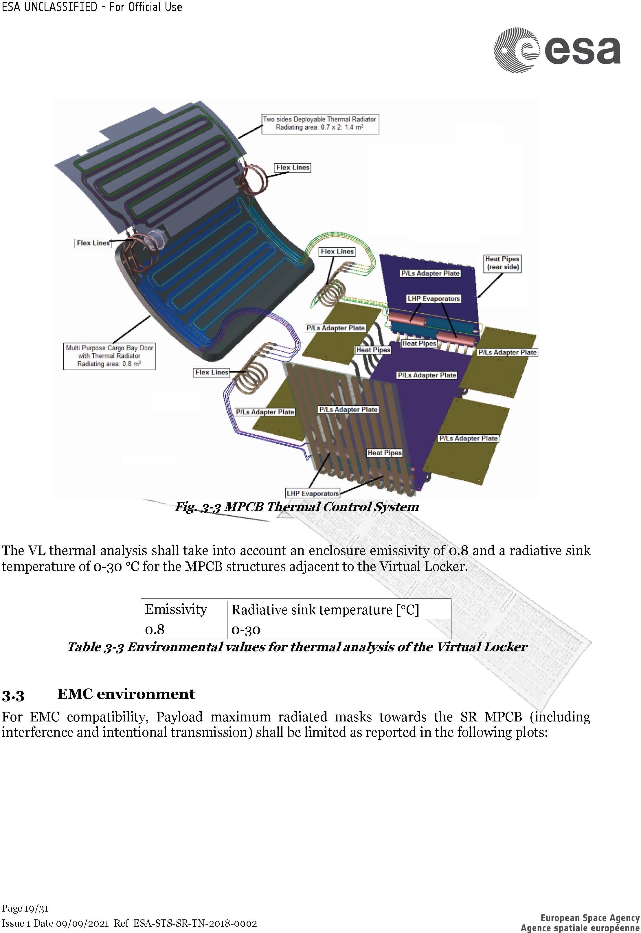
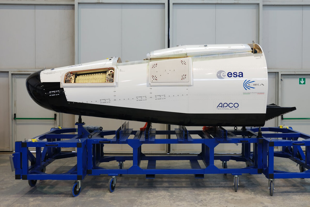
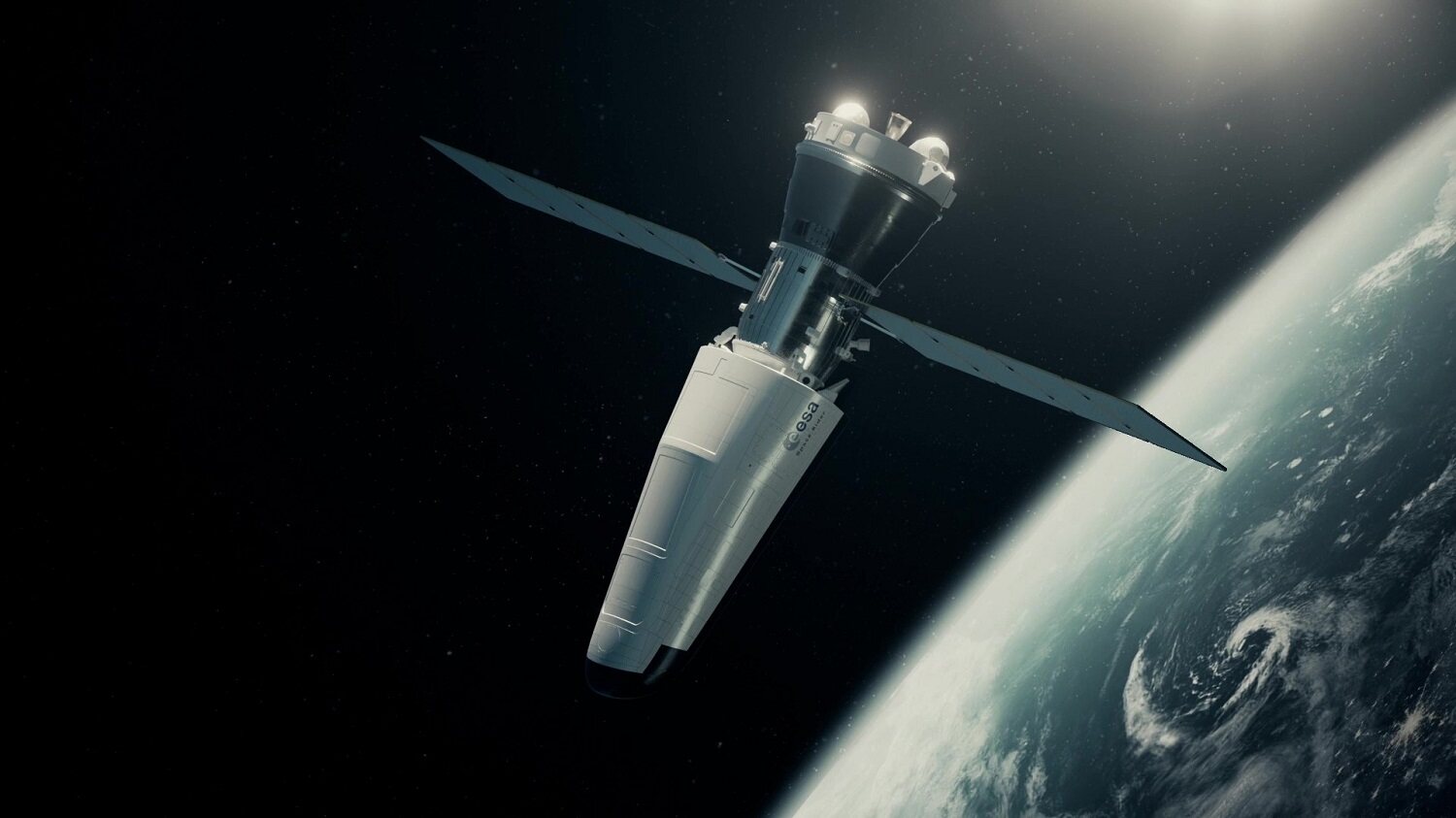
ESA’s three-view orthographic blueprints served as the sole geometric truth for vehicle contours. The official User Guide was used to position cargo bay doors, service access panels, and reaction control thrusters; ESA conceptual renders and hardware photographs guided livery boundaries and material properties; photographs of the predecessor IXV vehicle were referenced strictly to resolve obscure hardware details without dictating Space Rider’s outer mold line.
Version 1 (v1)
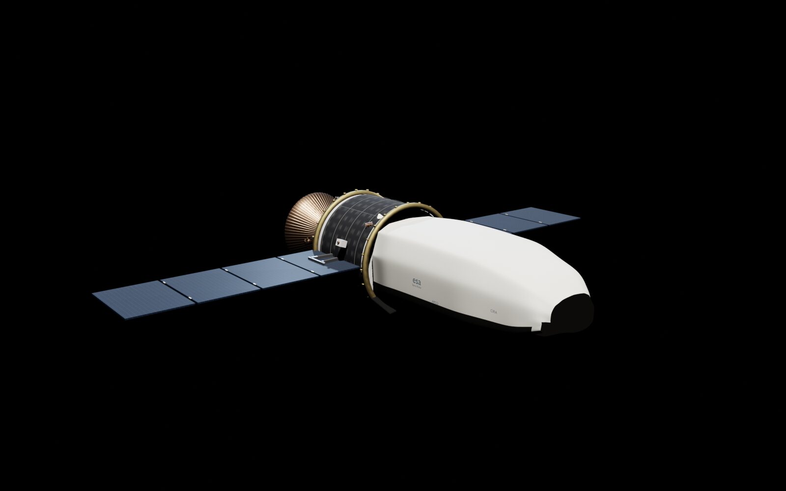
Version 1 was primarily an exploratory draft, though the final output was unacceptable for production. In just two days, I built out the full vehicle assembly: re-entry module, service module, propellant tanks, nozzles, solar arrays, navigation lights, and decals.
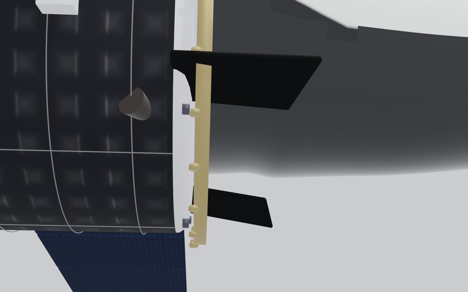
However, inspecting the renders revealed numerous flaws: the nose was far too pointed; cargo bay doors protruded unnaturally from the fuselage curvature; wingtip lights ended up in the wrong coordinates; and the model inadvertently featured vertical stabilizers (which do not exist on Space Rider) alongside thermal protection tile details borrowed erroneously from IXV.
I reshaped the sharp nose into a blunt dome, purged detached objects from the main body, and deleted the erroneous vertical fin, flaps, door panels, and surplus brackets.
My takeaway from v1 was that high visual completeness does not equal geometric correctness. Adding fine details too early makes subsequent proportional corrections vastly more expensive.
Version 2 (v2)
In v2, I established the canonical vehicle geometry by rebuilding the re-entry module from scratch. Early iterations used only 31 cross-sectional rings; I increased this to 91 rings with 32 vertices each, capturing the wedge profile that slopes monotonically from the tall aft section toward the chiseled nose.
This iteration also resolved three lingering issues:
- Fixed the right-hand decal mirroring problem by configuring independent left and right text objects;
- Replaced per-face thermal protection system (TPS) material assignments with a position-driven analytical shader;
- Discovered an 11% excess in fuselage height, compressed the overall geometry, and re-calibrated all dimensions against the blueprints.
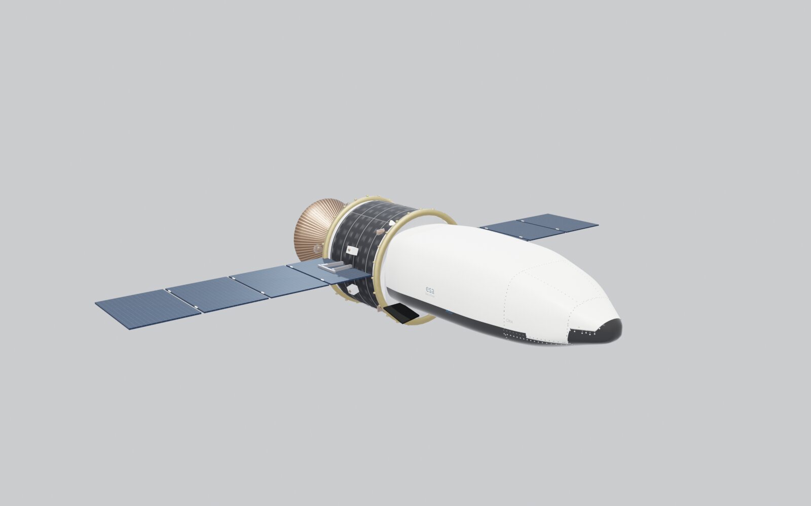
Once v2.720 was complete, the vehicle possessed its intended form. It became our protected baseline—every subsequent branch rollback returned to this milestone.
Version 3 (v3)
Starting with v3, I set up an automated inspection loop: selecting target regions, modifying a minimal number of vertices per cycle, saving and reloading, and evaluating changes in topology, materials, and vertex positions.
However, after running more than 60 iterations—each passing automated checks—the model showed virtually no discernible improvement. Local smoothness scores kept rising, but without a fixed global objective guiding the convergence path.
This branch was ultimately abandoned and rolled back to v2. The bottleneck in that workflow was evident: an optimization loop that only refines local metrics without anchoring to a global ground truth like orthographic blueprints can iterate endlessly without approaching the final deliverable. In AI-assisted workflows, defining unambiguous, verifiable criteria is critical.
Version 4 (v4)
In v4, I tried radial reconstruction to eliminate pinch wrinkles at the nose apex. While the wrinkles disappeared, the nose became artificially shortened, the ventral curvature flattened, and the black TPS boundary contracted.
Side-by-side comparison between v4 and v2.720 showed that the new version was inferior overall, prompting another complete branch rollback.
Following this rollback, I instituted a strict rule: never sacrifice verified global proportions and livery boundaries to resolve localized surface imperfections.
Version 5 (v5)
My core principle for v5 became: diagnose display artifacts first before touching geometry. Retaining v2.720 as the foundation, I first locked the camera strictly to the blueprint overlay view.
During this process, two seemingly severe geometric defects turned out not to be geometric at all. A visible weld seam across the nose tip was merely a shading artifact that vanished instantly once Weighted Normals were enabled—without moving a single vertex. A depression band across the nose was caused by inverted winding order on 82% of the base faces, which resolved after recalculating normal vectors.
From that point on, I switched viewport shading to a clay material under raking light before evaluating geometry. Dark materials disguise flat planes as depressions, while uniform lighting conceals surface waviness. I banned Taubin smoothing, which had previously collapsed convex nose sections into multiple dimples, restricting subsequent cleanup strictly to outward normal-based depression corrections.
When fine manual vertex adjustments eventually produced a crease line across the nose, I adopted a different approach: fitting the entire nose in a single analytical pass using B-spline cross-sections combined with symmetric Fourier series (91 coefficients in total, achieving a fitting RMS of 2.6 mm).
A minor crease remained at the tip because the control cage terminated in a pseudo-pole. This confirmed that the underlying topology was flawed, meaning vertex shifting could never resolve the issue. I deleted the terminal face loop entirely and rebuilt the apex into a clean polar fan, achieving zero surface dimples for the first time. Topological flaws cannot be solved by simply tweaking vertices!
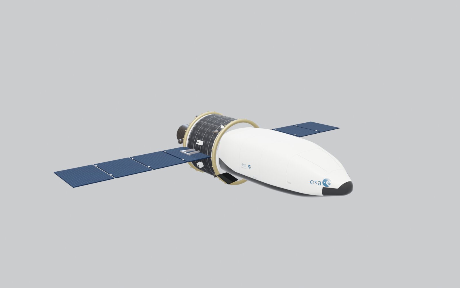
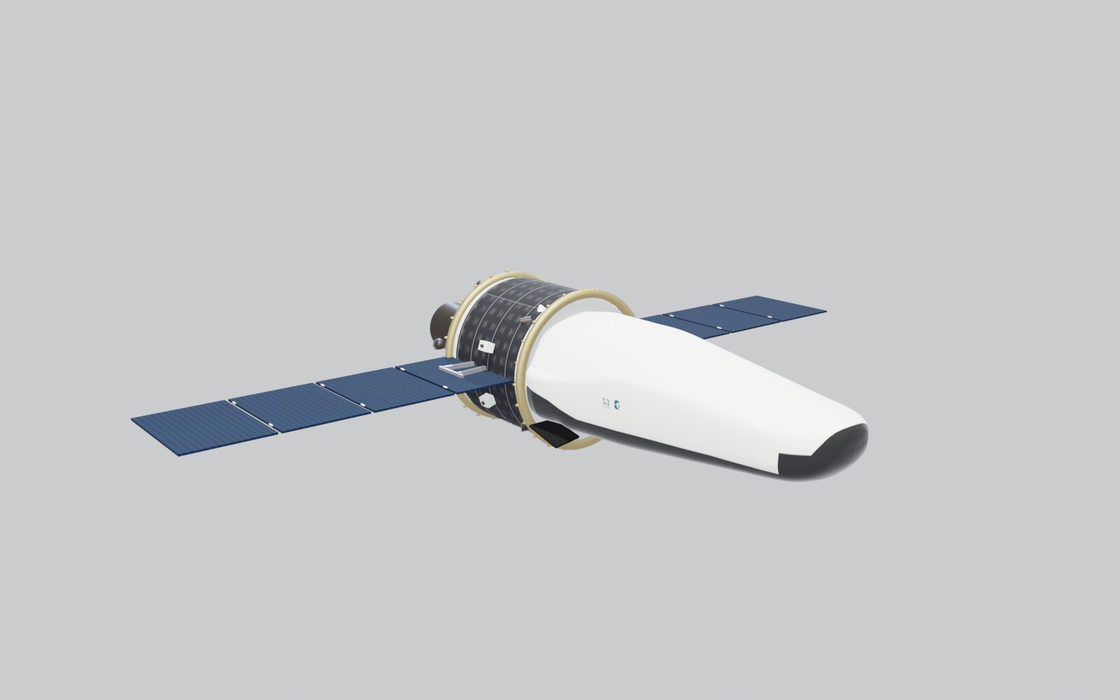
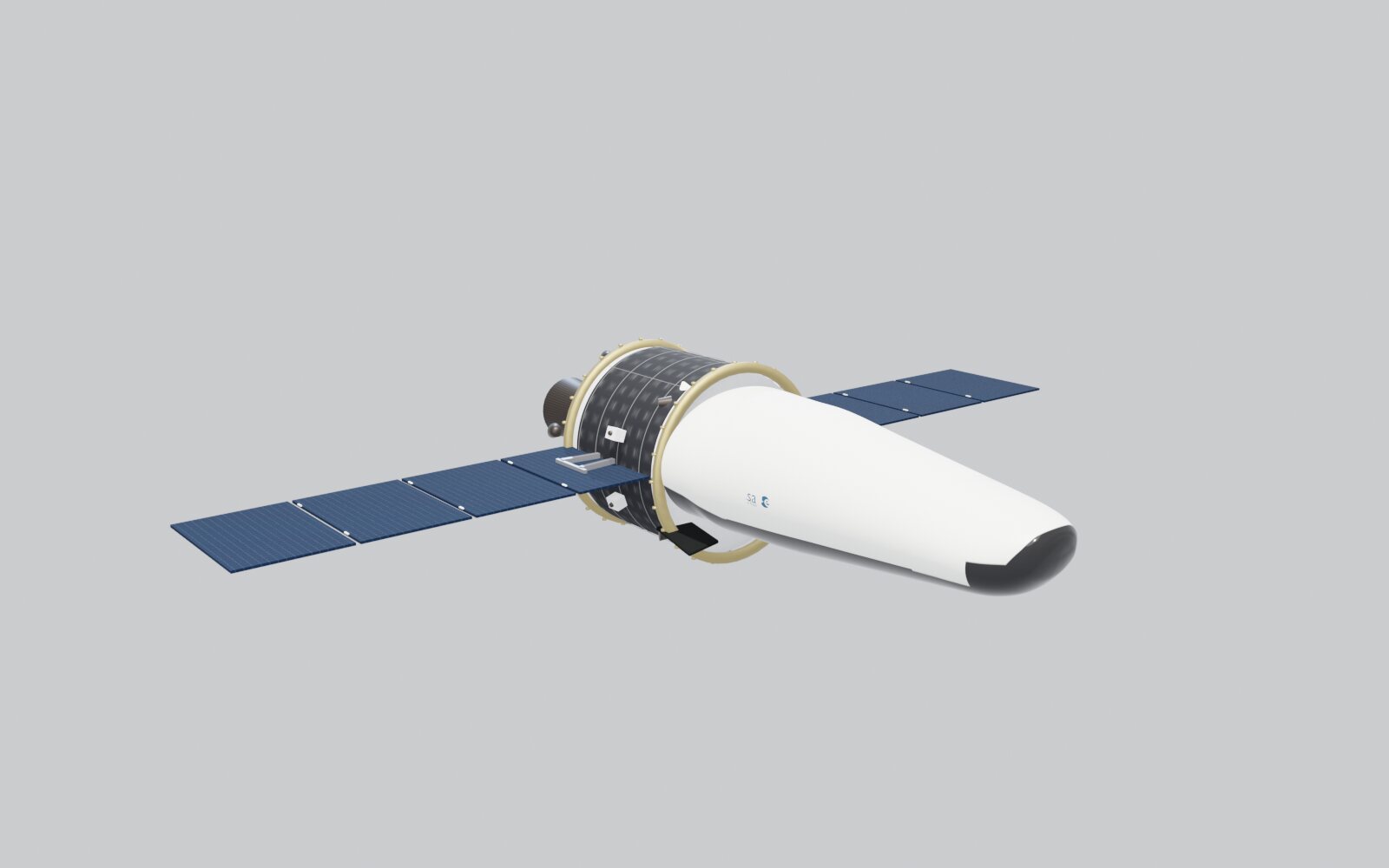
Blueprints as the Ultimate Ground Truth
During the first rigorous blueprint overlay inspection, I identified substantial deviations: the mid-fuselage roof was 103 mm too high, while the nose was 60–180 mm too low.
I remapped the fuselage along its longitudinal stations onto B-spline curves fitted directly to blueprint profiles. Following this adjustment, side-view deviations were bounded within ±6 mm, and top-view deviations within ±8.4 mm.
Every cross-section was also projected onto fitted ellipses for verification, resulting in a worst-case discrepancy of 2.1 mm and an RMS deviation of 0.5 mm.
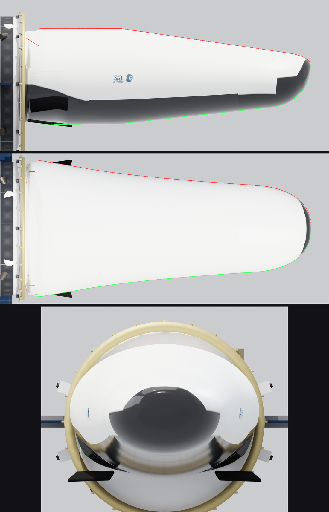
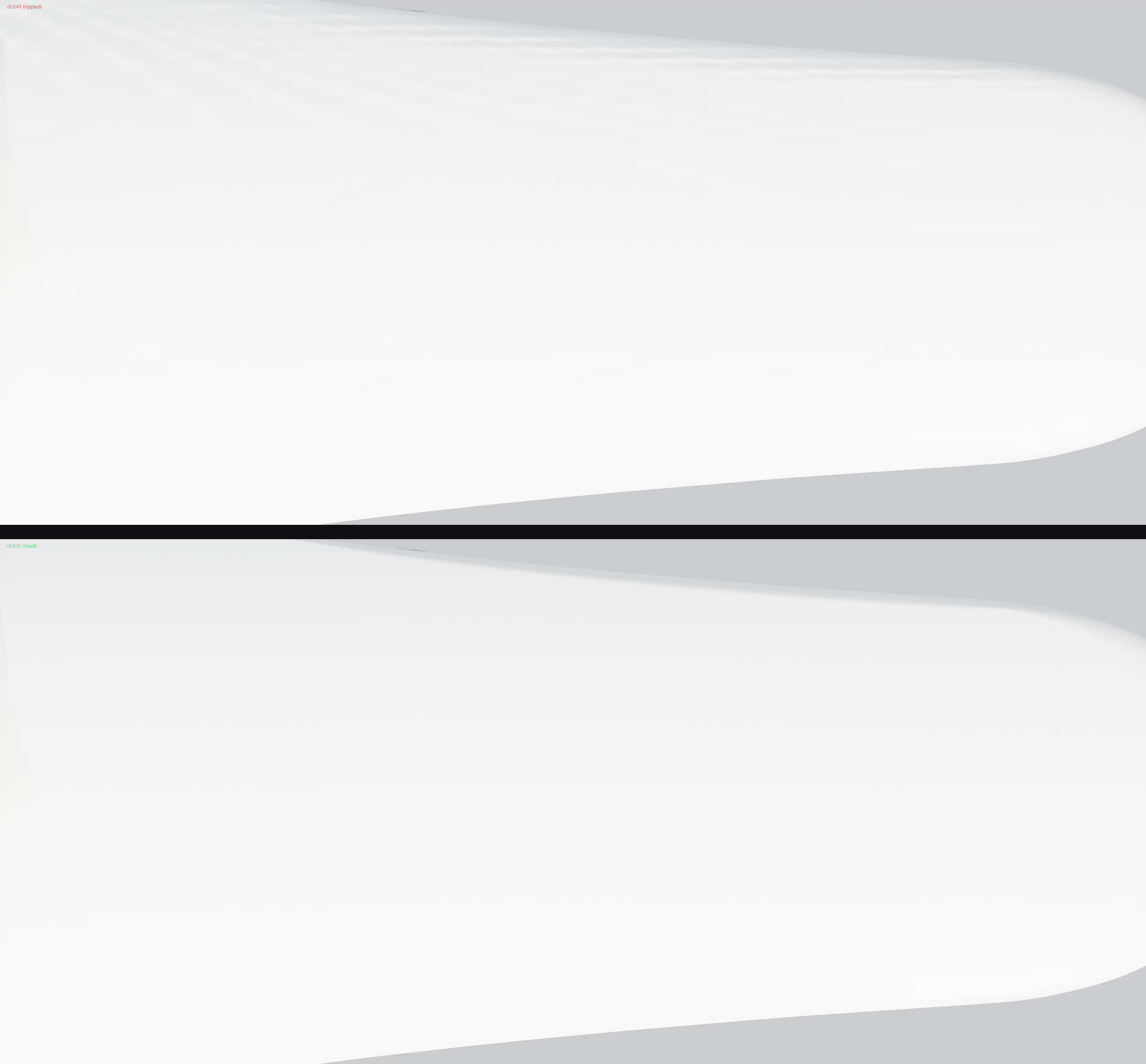
Surface smoothing followed the same analytical rigor. An initial 4 cm grid-based limiter passed all numerical checks but left visible ripples with 2.39 mm RMS across the outer shell. Transitioning to a mesh-free analytical limiter reduced surface roughness to 0.09 mm RMS.
Final Verification and Deliverable Metrics
The final model satisfied all client delivery tolerances:
| Inspection Item | Result |
|---|---|
| Side view vs. blueprint | Within ±6 mm |
| Top view vs. blueprint | Within ±8.4 mm |
| Aft deck planarity | ±0.6 mm |
| Cross-section ellipse fit | Worst-case 2.1 mm, RMS 0.5 mm |
| Number of dimples / depressions | 0 |
| Surface roughness | 0.09 mm RMS (reduced from 2.39 mm) |
| Pre/post cleanup pixel difference | 0.00000 |